Both ECU makers and integrators fail to provide consistent technical data, so that most of the informatrion gathered in this page are compiled from various sources. Due to the lack of accuracy and reliability of some information, I decided to adopt a ranking system that ranges from the "Sure" to the "Unsure".
[S]: (Fairly) Sure
[M]: May be (probable but needs further checking)
[U]: Unsure
Dsiclamer: Information from this site is provided as is, with no warranty of any kind from the author. Information is subject to change without notice. No support and no material is available from the author.
Modern vehicles are equipped with a variety of environmental, safety and other features that require some form of computer control. All EFI vehicles have at least one electronic modules (including a computer) that controls the fuel injectors and usually the spark timing; theese modules are called ECU (Engine Control Unit) or ECM (Engine Control Module). Other features such as electronic transmissions, antilock braking systems and air bags require additional electronic modules for monitoring and control. Modules communicate information electronically between themselves via a bus. A bus is just a computer term for a wire (or set of wires) that carries electronic messages from one part of a computer-controlled system to another. The bus in most EFI vehicles consists of a single wire that carries a 5-volt serial data stream. Each module that is connected to the bus may broadcast and receive discrete packets of information via the bus.
OBD stands for On-Board Diagnostics and has been on most vehicles since 1981. The first generation of OBD (or OBD I) was originally designed as a means to monitor various systems on a vehicle (i.e. fuel injection system, ignition system, emission system, etc.) and detect any failures it sees. While the vehicle is running the computer will illuminate the MIL (Malfunction Indicator Lamp: either a "Check Engine" light or a "Service Engine Soon" light) on the dashboard to warn the driver that a fault has been detected. At that point, the computer is programmed to generate and store a numeric fault code (two or three digit code) that is associated with the failure. This is when a Code Reader becomes useful. OBD I covers the years of 1981 through 1993. OBD I was not named until the emergence of OBD II. This second generation of OBD was introduced universally in 1996 as part of a government mandate to lower vehicle emissions pollutants. These OBD II systems are found in vehicles built from 1996 to present. This recent system is a far more advanced and precise version of the first generation but the concept is still the same. The computer still monitors vehicle systems to look for faults, vehicles computer still uses an MIL indicator to warn the driver of problems, and codes can still be pulled to identify the systems or circuits where the problem was detected.
History of Diagnostics
ALDL (Assembly Line Diagnostic Line) is a proprietary GM communication protocol that allows conversation between ECU and an external device. From the ALDL protocol, various data formats and communication speeds are reported: Apparently, a lot of GM US cars fitted with the early ODB ECU's adhere to the ALDL 160 baud or to the ALDL 8192 baud (for Type P4, P6 and P66 ECU's) . Various types of ALDL connector can be found.
To our knowledge, there have been at least four different ALDL connectors used world wide (and probably more exist too!).
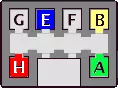
6 Pin Australian connector
In Australia, the VN and VP models used a 6 pin connector. The diagnostic link, a paper clip (red dotted line), is used to enable "flashing diagnostic mode", and is not described here. The data from this connector is at 160 baud when the diagnostic link is a 10k ohm resistor. You'll find this connector under the glove box on the VN/VP.
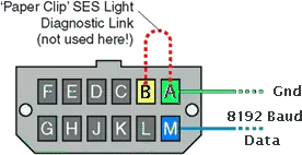
12 pin US style connector
Here's a view of the 12 pin US style ALDL connector, and where to connect the above circuit to. The pin numbering scheme is the same as that used on the VN/VP Holden Commodores (but those vehicles used the 6 pin connector shown above). This diagram is courtesy Carsten Meyer.
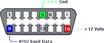
16 pin OBD-II style Australian Connector
Later Australian Commodore models (VR, VS, etc.) use a 16 pin OBD-II style connector, but the pinouts are unique to Australia. This connector is located under the steering wheel.
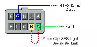
10 pin European (Opel) Connector
![]() ALDL modes [M]
ALDL modes [M]
There are three classes of vehicles that have been produced by GM since 1982.
Resistive control
The first set of vehicles are those whose data streams are controlled by placing a resistive value from pin B of the ALDL connector to pin A of the ALDL connector. The vehicles, called resistive control (RC) represent the largest portion of GM vehicles produced to date. These vehicles have the following modes:
Pulse Width Modulated
The second class of vehicles are those that are controled by shorting pin B to pin A. This class of vehicles is controlled by the amount of time pin B is shorted to pin A and is called Pulse Width Modulated (PWM) vehicles. To control the modulation, the cehicle sets up a 0.500 second time frame during which it calculates the ground time. The following list shows the relationship of the ground time to the mode chosen.
| msec. | Mode |
| 0 - 35.7 | Normal State |
| 35.8 - 107.1 | ALDL Mode 1 |
| 107.2 - 178.6 | ALDL Mode 2 |
| 178.7 - 250.0 | ALDL Mode 3 |
| 250.1 - 321.4 | ALDL Mode 4 |
| 321.5 - 392.9 | ALDL Mode 5 |
| 393.0 - 464.3 | ALDL Mode 6 |
| 464.3 - 499.9 | Diagnostic Mode |
GM30
The third class of vehicles is called GM30. The description of these vehicles can be found in the GM document XDE-5024
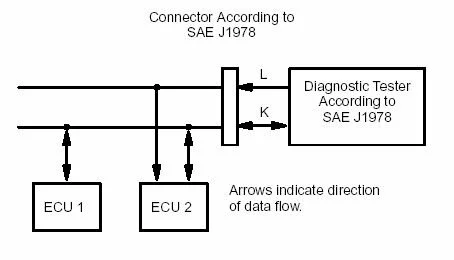
ISO 9141 is an international standard for communications between automobiles and diagnostic testers. It specifies a serial data communication bus between the vehicle’s Electronic Control Units (ECUs) and the diagnostic test SAE OBDII Scan Tool (SAE J 1978). ISO 9141 has been adopted by the California Air Resources Board for all cars sold in California with feedback fuel control systems. Similar rules are being adopted in New York, New Jersey, Massachusetts, and Maryland, and are expected to affect the design of most cars sold in the United States.
ISO 9141 specifies different logic levels for the Receiver and Transmitter.
Receiver Logic Levels:
Emitter Logic Levels:
Where Vbat is the battery's voltage
Loading resistances
| K-line | L-line | |
| Logic “0” / Receiving | Ground | from 50 k to 110 k ohms |
| Logic “1” | Ground | 50 k ohms |
The primary form of communication is with the single-ended K-Line. The K-Line passes data bidirectionally, as well as transferring all address information during initialization. The K-line is pulled up to Vbat by a 510 ohms biasing resistor, and biased to ground through a resistor that may vary between 50K and 110K ohms [M].
![]() L-line [S]
L-line [S]
The optional L-Line is unidirectional and is only used to pass address information from the diagnostic tester to the ECUs during initialization. The L-Line is in a 1-state during all other events. The K-Line will mimic the L-Line’s address initialization.
Any desktop or laptop will do the job. Its performance shall be compatible with Windows 98 (and higher), NT4 (and higher) operating systems.
The simplest interrfaces are directly pluged to the ALDL connector and to the PC. Some are using a microcontroller (microprocessor) thus belonging to the class of "intelligent" interfaces. More and more IC's aer now available that integrates all or part of the interfacing functions.
ISO: International Organization for Standardization
http://www.iso.org
SAE: Society of Automotive Engineers
http://www.sae.org
Access to the ECU
https://club-calibra.org/pages/rep_ecu.htm
Advanced C++ programing hints for serial ports
http://home.ict.nl/~ramklein/Projects/Serial.html
ODBII
http://www.obdii.com/
Publications des normes ISO
http://www.softing.com/de/ae/normen.htm
RS232C page
https://club-calibra.org/pages/rs232.htm
The real thing, at last...
http://www.carlton24v.co.uk/aldl.htm
Cette page est destinée à mettre en commun un maximum d'information qui seront nécessaires pour l'élaboration du projet ECU2PC, lequel comprend la conception électronique et informatique d'une interface spécialisée.
Important: Les informations contenues dans cette page sont mises à votre disposition en l'état. L'auteur de ce site ne saurait en aucun cas être tenu responsable des conséquences d'une information erronée ou utilisée de manière inappropriée. Aucun support ni aucun matériel ne sera fourni par l'auteur.
![]()